The Ultimate Guide To Wedge Barriers

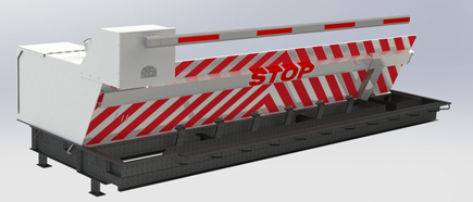
In the following discussion, recommendation is made to a surface of a foundation to which the wedge-style barrier is installed. For instance, in the detailed embodiments, the upper side of the support is considerably flush with the surface area of the structure. In such embodiments, the wedge-style obstacle might be installed directly to the surface area of the foundation. In other personifications, the top side of the anchor may be somewhat elevated over the surface of the foundation or somewhat recessed below the surface area of the foundation. 1 is a front perspective view of a personification of a surface-mounted wedge-style obstacle 10. As shown, the obstacle 10 is mounted to a surface 12 of a foundation 14(e. g., a superficial structure ). For example, the structure
14 and the surface 12 to which the barrier 10 is safeguarded may be made from concrete - Wedge Barriers. 2, the barrier 10 is placed to or includes a support or subframe (e. g., anchor 30 received FIG. 2 )safeguarded underneath the surface area 12. The bather 10 may be bolted to the anchor or secured to the anchor by various other mechanical fasteners. In the detailed personification, the barrier 10 includes a wedge plate 16, that includes a portion that is considerably parallel with the surface area 12 when the barrier 10 is in the withdrawed placement. In various other words, vehicles or individuals might overlook the obstacle 10 when the obstacle 10 is in the pulled back placement and experience slight altitude relative to the surface area 12 while on the obstacle 10. As reviewed carefully listed below, when the obstacle 10 remains in the deployed position, the wedge plate 16 is held and supported in an increased placement by a training device of the barrier 10. In addition, the components 18 might be bolted or otherwise mechanically combined to one an additional. In this manner, fixing or replacement of one or even more elements 18 may be streamlined and streamlined. That is, repair or substitute of solitary parts
18 might be done quicker, quickly, and expense efficiently. FIG. In specific embodiments, the anchor 30 might be a steel framework including plates, light beams(e. g., I-beams ), and/or other frameworks that are protected within the structure 14, which may be concrete. At the surface area 12, an upper side 28 of the support 30 may be at the very least partially subjected
, consequently allowing the attachment of the obstacle 10 to the support 30. g., threaded openings)in several light beams or plates of the support 30 may be revealed to the surface 12. In this manner, bolts 32 or various other mechanical fasteners may be utilized to safeguard the barrier 10 to the support 30. As the obstacle 10 is placed to the surface area 12 of the structure 14, collection of debris and various other material under the obstacle may be minimized, and elements of the bather 10 might not be revealed to listed below quality settings. As suggested by recommendation character 52, the training system 50 consists of elements got rid of underneath the wedge plate 16. The elements 52 under the wedge plate 16 may include an electromechanical actuator, a camera, one or even more web cam surfaces, and so forth. Furthermore, the lifting device 50 includes a springtime setting up 54
The spring pole 58 is paired to a webcam(e. g., cam 80 displayed in FIG. 4) of the lifting device 50. The springs 60 disposed concerning the spring rod 58 are kept in compression by springtime sustains 62, including a taken care of spring assistance 64. That is, the fixed springtime assistance 64 is fixed about the foundation 14 et cetera of the bather 10.
Excitement About Wedge Barriers
The remaining force applied visit the website to
the cam webcam deploy the wedge plate 16 may be provided given an electromechanical actuator 84 or other actuator. The spring setting up 54 and the actuator 84(e. Wedge Barriers. g., electromechanical actuator)may operate with each other to translate the camera and raise the wedge plate 16.
As pointed out above, the spring setting up 54 applies a continuous pressure on the cam, while the electromechanical actuator might be controlled to put in a variable force on the camera, therefore enabling the training and reducing( i. e., deploying and retracting )of the wedge plate 16. In specific personifications, the continuous pressure used by the spring setting up 54 might be adjustable. g., electromechanical actuator) is impaired. As will be appreciated, the springtime assembly 54 may be covered and shielded from debris or various other elements by a cover plate(e. g., cover plate 68 website link received FIG. 4) that may be considerably flush with the raised surface 38 of the foundation 14. As mentioned above, in the deployed placement, the wedge plate 16 serves to obstruct gain access to or traveling past the barrier 10. For example, the barrier 10(e. g., the wedge plate 16 )might obstruct pedestrians or cars from accessing a property or pathway. As discussed over, the obstacle 10 is affixed to the support 30 protected within the structure 14,
front brackets 71. Because of this, the link assemblies 72 might pivot and revolve to allow the collapse and extension of the linkage settings up 72 during retraction and implementation of the bather 10. The affiliation settings up 72 cause motion of the wedge plate 16 to be limited. If a vehicle is taking a trip in the direction of the released wedge plate 16(e. For instance, in one condition, the safety and security legs 86 might be prolonged duringmaintenance of the barrier 10. When the security legs 86 are deployed, the safety and security legs 86 support the weight of the wedge plate 16 versus the surface area 12. Consequently, the training device 50 may be deactivated, serviced, eliminated, replaced, etc. FIG. 5 is partial viewpoint sight of an embodiment of the surface-mounted wedge-style barrier 10, highlighting the cam 80 and the cam surface areas 82 of the training device 50. Specifically, 2 camera surface areas 82, which are described as lower camera surface areas 83, are placed listed below the web cam 80. The lower camera surface areas 83 may be taken care of to the surface area 12 (e. As an example, the lower webcam surfaces 83 and the placing plate 85 might create a single piece that is secured to the anchor 30 by screws or various other mechanical bolts. In addition, 2 webcam surface areas 82, which are described as top cam surfaces 87, are placed above the camera 80 and coupled to (e. In other personifications, interfering layers or plates might be positioned between the surface 12 and the lower webcam surface areas 83 and/or the wedge plate 16 and the top camera surface areas 87 As mentioned above, the web cam
80 equates along the cam surfaces 82 when the wedge plate 16 is lifted from the pulled back placement to the deployed placement. In addition, as mentioned above, the spring setting up 54 (see FIG. 3 )may supply a pressure acting upon the web cam 80 in the instructions 102 using springtime rod 58, which may minimize the force the electromechanical actuator 84 is required to use to the webcam 80 in order to activate and raise the wedge plate 16. 1 )to the released setting(see FIG. 4). As shown, the webcam 80 includes track wheels 104(e. g., rollers), which contact and convert along the web cam surfaces 82 during procedure.